
I’ve done a lot of small hacky home electronics projects, but this is my first time writing a blog post about one. Here goes…
My wife and I live in a typical ’40s New Zealand house (which has minimal insulation in the ceiling, none in the walls and single-glazed windows), and like most Kiwis our normal winter behaviour is (at least some of the time) to simply put up with the cold.
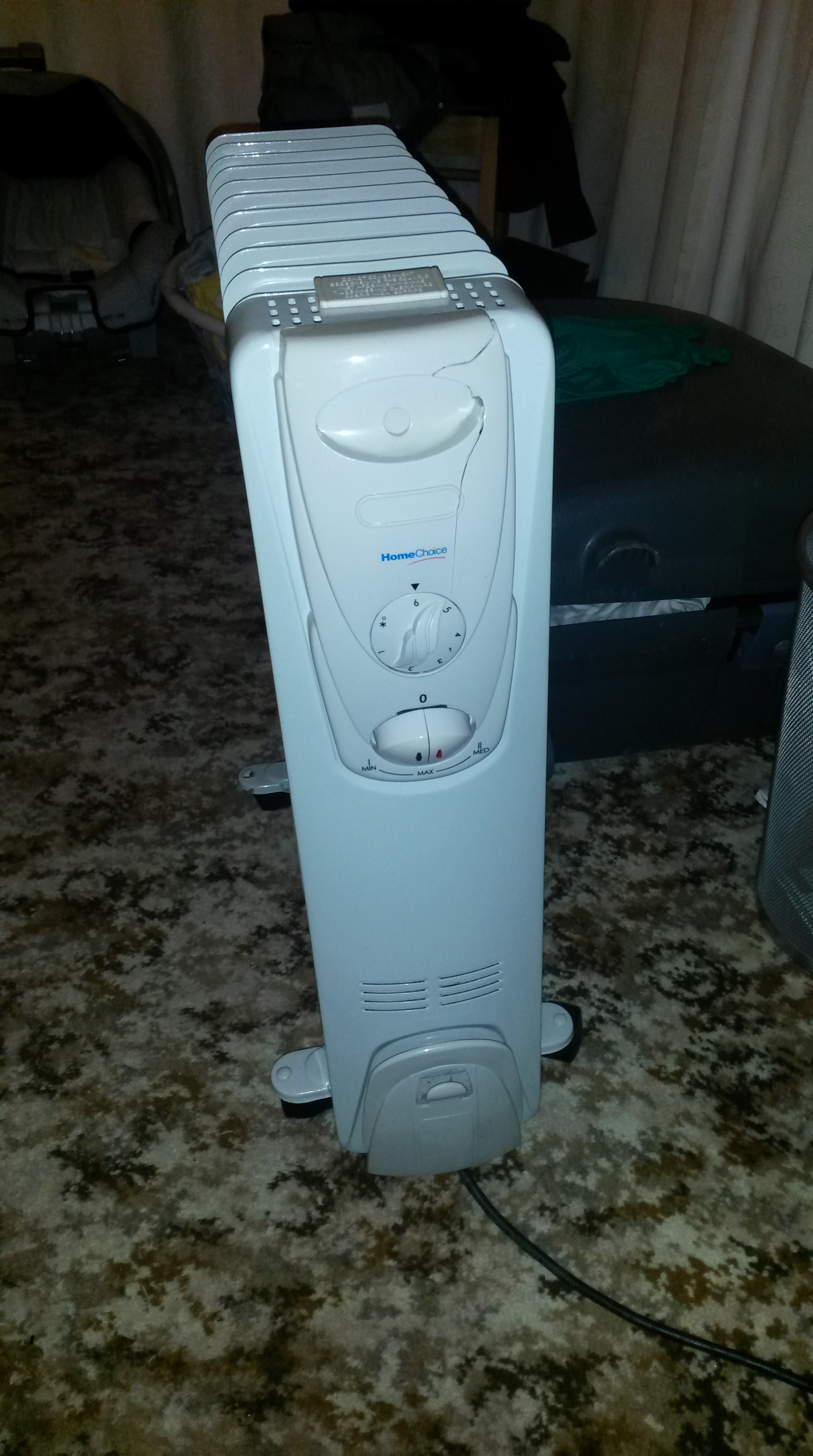
Upon having a baby, this had to change somewhat for a while, so we turned to the trusty electric oil fin heater to keep our bedroom warm. This has a basic mechanical thermostat, numbered 1 – 6 which corresponds not so much to the room temperature as the heater temperature.
What this means is that the thermostat needs to be constantly adjusted as external factors change (such as the temperature outside). With practice one can get quite good at this, but for me it was an opportunity to make a new gadget.
First, though, I went looking for a product that solves this problem – a plug-in thermostatic controller. I found something which in Australia and New Zealand is sold as the HeaterMate.

This appeared to be exactly what the doctor ordered, but turned out to be quite unimpressive. The first problem is that the plug of an appliance drawing ten amps can easily have a bit of warmth to it, and relays have their losses as well. I think this is why, once it’s been in use for a while the temperature that the HeaterMate thinks the room is becomes up to 4 degrees too high! The second issue is that the HeaterMate’s approach to temperature control appears to be frustratingly naive. It turns the heater on until the room temperature reaches the setpoint, then turns it off again until the temperature is 1 degree below the setpoint. The heater itself stores a reasonable amount of energy, which compounds the problem by making it undershoot and overshoot this range. Furthermore, the location where a heater plugs into the wall is (a) usually not a convenient spot for temperature controls and (b) in some cases may be close to the heater itself (in the case of panel heaters).
What I wanted was something that could find the right power level for the heater, and maintain that to provide a near-constant room temperature, and I thought that the PID algorithm (which is what makes your cruise control work) might be exactly what was needed. I also figured that it would help a lot to separate the temperature sensor from the part where the heater plugged in – more on that later.
I had a go at explaining PID at this point in the post (because a really simple explanation would have been extremely useful for me), but it turned out to be far too long. I don’t want to bore anybody, so I’ll see if I can write that up later in case it’s interesting.
Anyway, onto the implementation.
I used an Arduino, and the super handy PID Library. This allowed me to set an output range of 0-100, which I used as a percentage power to run the heater at. I would then control the heater using really slow pulse width modulation, which initially was a 4 minute cycle (so, 75% power would mean that the heater was on for 3 minutes and off for 1 minute). I had a few of these lying around, so I simply got my Arduino to send the 433MHz on and off codes to one to control the heater. I switched to a 20 minute cycle after burning out the cheap relay within a couple of weeks…

Because I’m lazy, I’ve used the Seeduino Lotus, which is an Arduino Uno clone with a bunch of Grove connectors on it. This allows me to easily plug in bought modules (the I2C LCD screen, the temperature sensor, the buzzer) and use the connectors (which each have GND, +5V and two I/O lines) to connect my own peripherals (the 433MHz transmitter and the IR receiver).
Mainly because I didn’t have any buttons handy, I decided to use a spare remote control to control the thing, which gives me a luxurious set of “buttons” to control it with. All I’ve implemented so far is adjusting the temperature and the backlight brightness, but my intention would be to build a menu system where all aspects of the device can be adjusted.
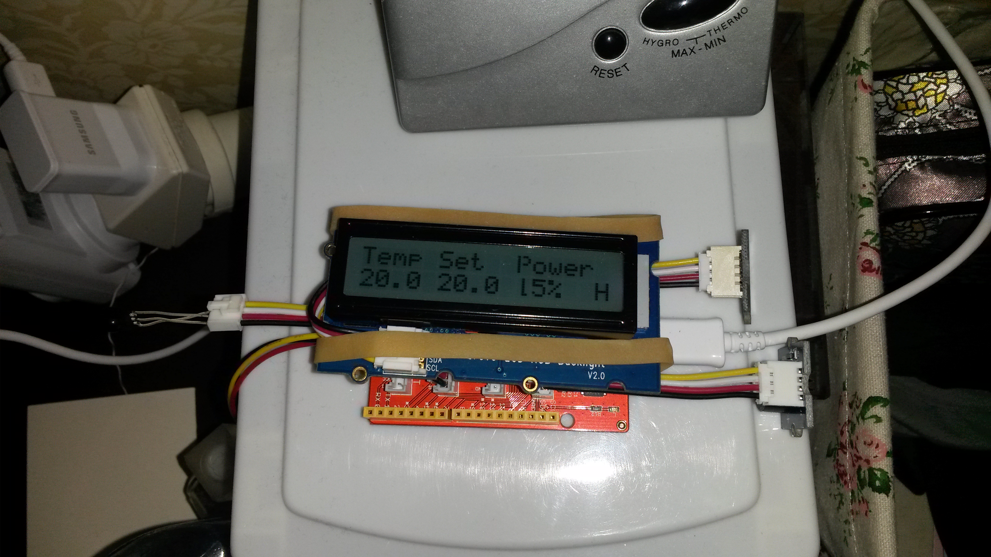
I have not done much experimentation with tuning, but I used a proportional value of 45% (meaning that a 1 degree error will increase the power by 45 percentage points) and an integral value of 0.05, meaning 0.05 percentage points per degree error per second, or 3 per minute. I did not use a differential component. Despite the lack of tuning, I have had excellent results. This approach keeps the room temperature with 0.1 degree of the setpoint most of the time, and adjusts well to changes in conditions.
In the image above, the room temperature is exactly on setpoint, and the power level shown is the integral term which is doing its job of keeping it there. If something changes (like me opening a door or upping the setpoint), the proportional term helps to quickly react.
I feel that a product could be made of this (considering that the HeaterMate appears to be a successful product), but I don’t think I’d actually try to take it that far. My vision for it is that the controller unit would be a small battery-powered device that could be mounted on the wall. If I took this any further, the first things on my todo list would be:
- Use an SSR for the plug-in unit for silent, fast switching
- Use a larger display, that looks good without a backlight and can display information in a prettier format
- Add a few buttons to the controller
- Add timer functionality (because why not)
- Add an alert feature – it could start beeping or at least light an LED if it becomes unable to achieve the desired temperature (due to the failure of the heater or something)
- It could control multiple heaters in a zone
- It could provide power usage estimates, as it would know when the heater was on (and could be told the power consumption of the heater when on)
My code, which is pretty messy, is up at https://github.com/GeorgeDewar/pid-thermostat. Finally I’d like to apologise for the formatting of this post. First time wordpressing, you see…

hello that you used sensor for measuring the temperature
LikeLike
I used the temperature sensor that comes with the Grove starter kit because it’s what I had lying around. Any thermistor will do though, as I understand it. This one claims “1.5C” accuracy. It reads about 1 degree above my other cheap thermometer, but seems to be pretty consistent about that. I had to keep it a few centimetres away from the backlit LCD or it would read high.
LikeLike
hallo what is Wire.h
LikeLike
Wire.h is an Arduino library for communicating with I2C devices (a common 2-wire protocol). I2C is used in this project for talking to the display, so I think the Wire library is there as a dependency of the display library.
LikeLike
Thanks for this post, I implemented control of our nursery oil fin heater using openhab and a sonoff TH16 (which has a temperature sensor) and had the exact same problem with overshoot. I’m not using hysteresis though, rather just setting minimum on and off times to prevent flapping. This means that once the room settles close to setpoint (after initial overshoot) it stays relatively close with a minimum on time of 60 seconds and off time of 5 mins (effectively minimum duty cycle of 20%, if it’s going to turn on at all).
I was just thinking about implementing a duty cycle with PID as a better option to compensate for the residual heating. I take your point about destruction of relay though… Currently I’m using the 16A relay in the sonoff to control a 1kW heater, so there’s plenty of headroom there. I guess I’ll come back to post if implementing this kills my sonoff. An SSR would be a neater option, though would require heatsinking etc and I really want to apply a slightly higher threshold of known safety in the nursery than my average projects…
Of course as summer sets in (also in NZ!) I might have to start thinking about solutions to cool the nursery at night instead…
LikeLike
Hi, I like the details of this project especially going from problem to solution, giving the pitfalls you have encountered. I use SSR units at work and they are very reliable but have one flaw , they nearly always fail in the on position and continue to heat. Because of this a second relay or control circuit to factor this in is essential. You could have an overheat sensor or something that cuts the power to the ssr. This is just information don’t take it as any form of negative. I am impressed with your solution. I am looking at the NodeMcu which is for controlling things via wifi.
LikeLike
With those PI values, how long does it take to ” settle in” on startup?
I’m doing something vaguely similar and I get serious oscillation (due to the integral term) before settling in.
I guess it’s serious oscillation in the output, not on the input, so you wouldn’t even notice unless you were watching, so maybe it doesn’t matter…
LikeLike
Hi Rick,
On first startup, we get a slightly annoying spike of a degree or two, as the integral term reaches 100% before the setpoint is reached, then takes a while to come back down again.
I have not timed how long this phase lasts but I would guess an hour or so. I think it could be solved with better tuning.
Once it’s up to temperature, there is no discernable oscillation in the room temperature. However, I have desired to but never got around to measuring and graphing the oscillation in actual output.
The startup phase was not a great concern to me as for us the intended purpose was to leave it on for extended periods of time. It also does not occur if the room starts off above the setpoint, and then gradually drops (e.g. You turn it on before the room starts getting cold). It only happens if the room is significantly below the setpoint when the unit is turned on.
LikeLike
an old thread but in case this is useful to someone you have to scale your sampling rate to the step response time of your system. As in if you just turn the heat on how quickly does the temp change ? Your sampling rate, and integral scaling should reflect this type of time scale to get reasonable start up results. sampling 100 times a second (for instance) doesn’t make sense if it’s going to take 15 seconds to see a temp change. any way two cents worth. maybe one and a half.
LikeLike
Dear Sir!
Thanks your post. Can you send me your schematic for this project?
LikeLike
Hi George, I’m interested in doing a project very much like this but on a larger scale. I’d be very interested in having a chat with you if possible. Could you please email me your details?
LikeLike
Sure thing! I’ve sent you an email.
LikeLike